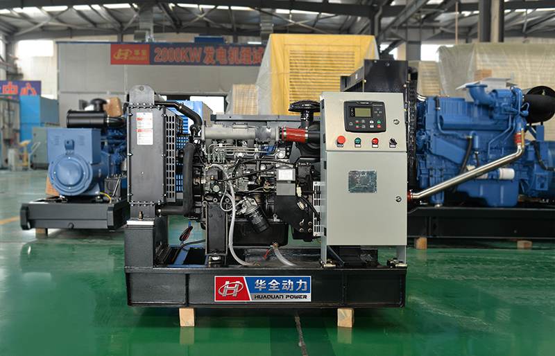
As we all know, the poor performance of the original components of the generator set will cause the generator to encounter some failures during operation: no power generation, low voltage instability, high power generation voltage, and high generator temperature. Today I mainly explain how to detect 5 components to avoid these problems.

- Stator detection: First, check whether there are scratches on the surface of the stator and the wire. The second is to detect whether the stator winding is short-circuited. Use the R×1 ohmmeter to check between the winding leads, which should be below 1Ω, otherwise, the stator should be replaced.
- Rotor inspection: First, there should be no scratches on the surface of the rotor, otherwise it indicates that the bearing is loose, and the front and rear bearings should be replaced. The surface of the collector rings should be smooth and smooth, and there should be no oil stains and foreign objects in the groove between the two collector rings. The second is whether the rotor winding is grounded. The third is to check whether the rotor winding is an open circuit or short circuit. The fourth is the maintenance of the rotor shaft and collector ring.
- Detection of brushes and brush holders: First, check the length of the brushes. The length of the brushes outside the brush holder is 10.5mm, and the use limit is 1.5mm. The second is to detect the brush spring pressure. When the brush protrudes 2mm from the brush holder, the reading indicated on the balance scale is the brush spring pressure, which should be 200~300N. If the spring elasticity is too small, a new brush should be replaced. 3. When replacing the brush, first put the brush spring and new brush into the brush holder, then clamp the brush wire with pliers to make the brush height reach the specified value of 10.5mm and then use an electric soldering iron to weld the brush wire. and brush holder.
- Bearing inspection: Rotate the bearing by hand to check whether there is abnormal sound and jamming. If there is an abnormal sound, it should be replaced.
- Rectifier detection: use the kΩ range of the multimeter, the negative needle is connected to the B terminal, and the positive needle is respectively connected to P1, P2, P3, P4 for detection, and vice versa to check the conduction of the positive diode of the rectifier;
Make the positive needle take the E terminal, and the negative needle take P1, P2, P3, P4 to test, and vice versa, test again to check the conduction of the negative diode of the rectifier. If the diode conducts in the forward direction and does not conduct in the reverse direction, it is normal.


